TM 11-5821-333-30
6-32. TEST ADAPTER SWITCHES
a. Replacement of Multi-Deck Switches S1, S2, S3, S4, S5, S6, and S15.
This task covers: a. Removal
b. Installation
INITIAL SETUP
Tools
Expendable Supplies
Tool Kit, Electronic Equipment, TK-105/G
Tiedown Straps
Equipment Conditions
Solder
Interconnecting device removed from chest (paragraph 6-22).
REMOVAL
1.
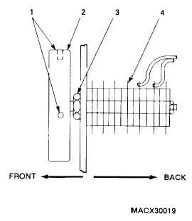
Use key set, Note position of switch, Loosen
two set screws (1) securing knob (2) to
switch (3). Pull knob off switch.
2.
3.
4.
5.
6.
Loosen and discard hex nut (4) and lock-
washer securing switch to front panel.
Pull switch from rear of front panel.
Use diagonal cutters to cut and remove any
tiedown straps that interfere with desolder-
ing.
Tag wires, and desolder from switch.
Remove switch.
INSTALLATION
1.
2.
3.
4.
5.
6.
Solder wires to terminals of switch.
Remove wire tags.
Insert switch in front panel opening aligning
tab.
Thread and tighten hex nut (4) and lockwash-
er supplied with switch to secure switch to
front panel,
Replace any tiedown straps removed.
Use key set. Position knob (2) on the switch
(3), and secure by tightening two set screws
(1).
6-204