TM 11-5820-801-30
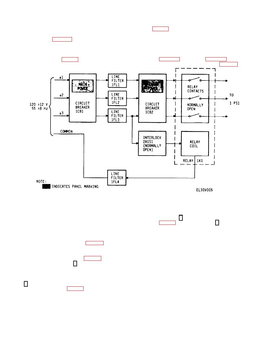
(K1, fig 3-3). When 2A1S1 is open 1K1 contacts cannot
2-13.
Safety Interlock
close. The three-phase primary power (120 12 V, 55
High voltage (-1000 V) is used to operate klystron
8 Hz) passes through the 1K1 contacts to 1PS1. Single-
oscillator 2A1V1 (para 2-7b). To protect personnel, a
phase primary power (120 12 V, 55 8 Hz) however, is
safety interlock is installed on the 2A1 chassis. When
not interrupted by the interlock switch. This single-phase
the 2A1 chassis cover is removed the interlock switch
primary power operates the temperature control circuits
opens and deenergizes Klystron Power Supply 1PS1, the
in 2A1 (para 2-11) and in 2A2 (para 2-10), vacuum gage
source of high voltage (fig. 2-5). Interlock switch 2A1S1
tube 2A3J2 and VACUUM meter 1M2 (para 2-9c).
is in series with the energizing coil of latching relay 1K1
Figure 2-5. Block Diagram of Safety Interlock Circuit.
desired channel.
2-14.
Channel Switching
b. The Waveguide Switches latch in either
a. A four-port waveguide latching transfer switch
position Channel 1 (port 1 connected to port 2 of the
(3A2/3A3) is used both at the signal input and at the
switch) (fig. 2-7) or position Channel 2 (port 1 connected
signal output ports of the redundant parametric amplifier
to port 4 of the switch); there is no OFF position. In each
system. The drive motors for the waveguide switches
position port 3 of Waveguide Switch 3A2 is available for
require 28 Vdc. This is supplied through split CHANNEL
a test signal input (to the standby channel) and port 3 of
SELECT pushbutton switch 3A1S1 on Remote Control/-
Waveguide Switch 3A3 is available to monitor the signal
Monitor Assembly 3A1 panel (S1, fig. 3-4). The input
output of the standby channel. Therefore, in waveguide
(3A2) and output (3A3) waveguide switch drives are
switch position 1; port 3 is connected to port 4 (Channel
connected in parallel and the waveguide switch position
2 standby), and in position 2, to port 2 (Channel 1
indicators are connected in series (fig. 2-6). Thus, when
standby).
The position of CHANNEL SELECT
the operator selects Channel 2 by pressing the right side
pushbutton switch 3A1S1 does not affect the specific
of 3A1S1, both the input (3A2) and the output (3A3)
operation of the Amplifier, Parametric AM-6602/MSC-
Waveguide Switches are switched simultaneously to
46(V) except that the switch position determines the
Channel 2 and the switch position indicators will cause
source of the RF input signal, operational or test, to each
the 2 half of CHANNEL SELECT pushbutton switch
channel.
3A1S1 to light (DS2, DS4, fig. 3-4). If a failure occurs in
c. In Serial No. 001, the noise diode assembly
either waveguide switch drive (or indicator) the panel
(3A13)
lamps, which are a part of the 3A1S1 assembly, will fail
to light. A hand (mechanical) switching knob on the top
of each waveguide switch permits manual setting to the
2-9


