
TM 11-6110-211-15
NOTES:
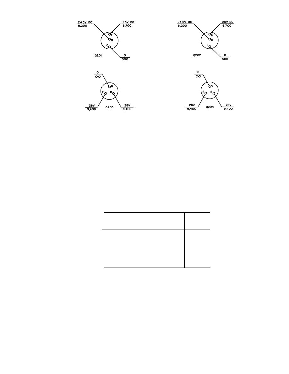
1. VOLTAGE AND RESISTANCE MEASUREMENTS ARE
SHOWN FOR EXTERNAL CIRCUIT POINTS WHICH ARE
NORMALLY CONNECTED TO THE TRANSISTORS BUT
WITH ALL TRANSISTORS REMOVED FROM CIRCUIT.
2. VOLTAGE READINGS ARE ABOVE LINE, RESISTANCE
READINGS BELOW LINE. READINGS MEASURED TO
GROUND. VOLTAGE READINGS WITH 20,000 OHMS-
PER-VOLT METER.
TM6110-211-35-5
3. RESISTANCES ARE GIVEN IN OHMS.
Figure 3-2. Amplifier, Electronic Control AM-3209/ASN voltage and resistance measure-
ments, transistors disconnected
(2) The minimum direct current between ter-
c. Performance Test.
minals H and I with an input signal of 1
(1) Vary the 400-cps input between termi-
volt should be 0.45 ma.
nals A and J to the values shown in the
(3) The maximum line current drawn from
following chart and use the voltmeter to
the 115-volt power source must not ex-
check the output voltages measured be-
ceed 200 ma during the entire test.
tween terminals D and E.
400-cps output
between
400-cps input between terminals A and J (millivolts)
terminals
D and E (volts)
3 to
18
50
---------------------------
9 to
30
100 -------------------------
14 to
36
150 ----------------------------
20 to
39
300 ----------------------------
22 to
38
500 -----------------------------
22 to
39
1,000 - - - - - - - - - - - - - - - - - - - - - - - - - - - - - - ----
3-5
