
TM 11-5820-801-30
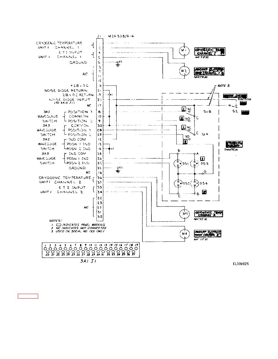
Figure 2-24. Remote Control/Monitor Assembly 3A1, Schematic Diagram.
b. Waveguide Channel Switching and Monitoring
latched into position. There is no neutral position; the
Waveguide Switches are in either position I[ (Channel 1
operation) or position [i (Channel 2 operation). The
use of 28-V drive motors in Waveguide Switches 3A2
indicating circuit, however, is continuously energized
and 3A3. To prevent the generation of RF noise by
since this circuit does not contain a component capable
hysteresis or other means, the drive voltage (28 V) is
of generating RF noise.
removed from the motors when the switching is
complete; that is, when the Waveguide Switches have
2-31
