
TM 11-6110-211-15
ing flag of an operable navigation indicator ( ID-
3-5. Troubleshooting
998/ASN, or equivalent).
When using the
a. Gerund. Procedures are outlined in the fol-
troubleshooting chart, refer to the parts location
lowing chart for localizing troubles within the
diagrams (fig. 34, 3-5, and 3-6) and the overall
various sections of the AM-3209/ASN.
Parts
schematic diagram (fig. 2-2).
l o c a t i o n is indicated in figures 34, 3-5, and 3-6.
Depending on the nature of the operational symp-
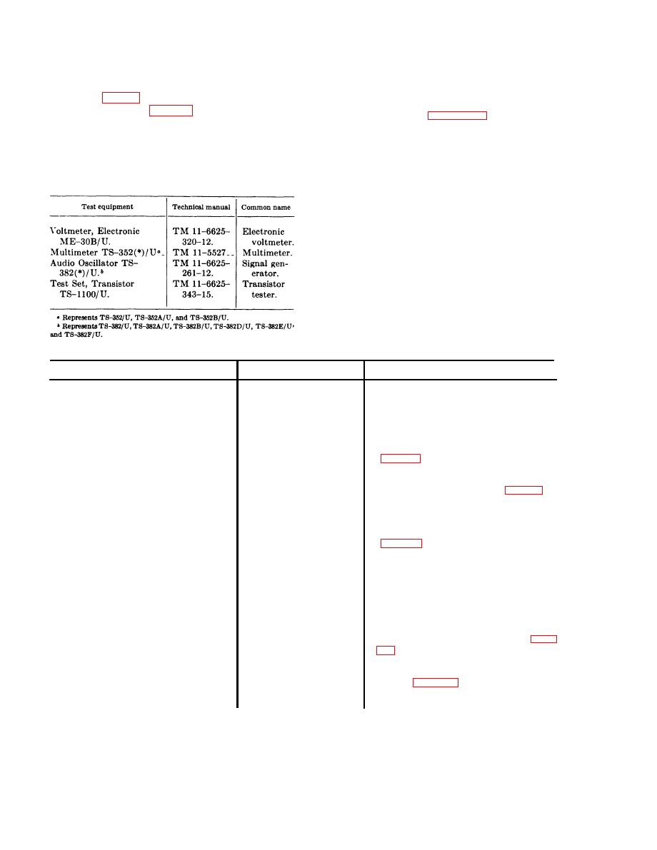
3-4. Test Equipment Required
toms, one or more of the localizing procedures will
The following chart lists the test equipment re-
be necessary.
quired for troubleshooting the AM-3209/ASN.
b. Use of Chart.
The troubleshooting chart is
Also included are the associated technical manuals
designed to supplement the operational and main-
and assigned common names.
tenance checks detailed in the electronic configura-
t i o n manual covering the aircraft in which the
AM-3209/ASN is installed.
The information
contained within the chart is based on symptoms
obtained when the AM-3209/ASN is connected
into a complete servo-loop system consisting of a
signal source and the motor-generator and warn-
ing flag circuit of an operable navigation indicator
(ID-998/ASN, or equivalent).
c. Troubleshooting Chart.
Symptom
Probable cause
Corrective action
Speed of motor-generator (in navigation
Check resistor values; replace faulty resistor.
Open calibrating resistor
indicator) is not constant or is too slow.
R201, R202, or R203,
Motor-generator inoperative due to lack of
Open resistor R210 ____
Check for approximately 25 volts dc at
control f eld voltage.
junction of resistor R210 and capacitor
(No output at
terminals 13 and 14 of connector P201.)
C205. Troubleshoot power supply.
Check dc resistance of transformer windings
Open winding on trans-
former T201A.
Defective component in
Check resistors R204, R205, R206, and
R212. Check voltages and resistances of
push-pull voltage
transistors Q201 and Q202 (fig. 3-1 and
amplifier.
3-2). Check bypass capacitor C201 and
resonant capacitor C202 for open or short
circuit. Replace defective component.
Open winding in trans-
Check dc resistance of transformer windings
former T201 B.
Defective component in
Check resistors R207 and R208. Check
fuses F201 and F202.
push-pull power ampli-
Check voltages
fier.
and resistances of transistors Q203 and
Q204. Check bypass capacitor C206 and
load capacitor C203 for open or short
circuit. Replace defective component.
Warning flag circuit inoperative. (No dc
Faulty power supply
Check resistor R211; check diodes CR201
circuit.
and CR202; check dc resistance of wind-
output at terminal 10 of connector P201.)
ings of power transformer T202 (para.
circuit. Replace defective component.
No 26-volt ac at excitation winding of
Open winding in power
Check dc resistance of power transformer
Replace defective
transformer T202.
generator of navigation indicator motor-
T202 (para. 3-7).
generator. (No ac output at terminal 8
power transformer.
of connector P201.)
3-2

