TM 11-5821-333-30
3-18. CONTROL PANEL (A1). Continued
DISASSEMBLY/ASSEMBLY
1.
REMOVE FLEX CABLE ASSEMBLIES W1 AND W2.
a.
b.
c.
d.
e.
f.
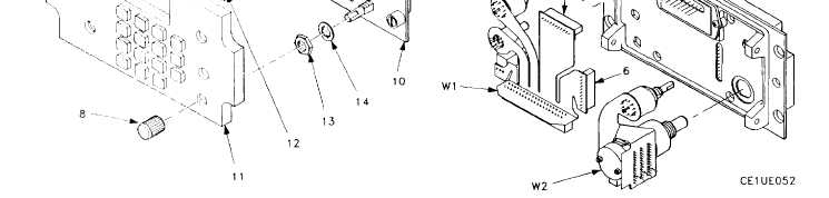
When removing W1, disconnect W1P1 (6) and W1P3 (7).
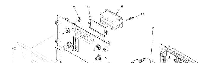
Loosen set screws on knobs (8) and remove all knobs.
Loosen six screws (9) securing front panel (10) to lighted panel/keyboard (11).
Remove lighted panel/keyboard (11) and gasket (12).
Remove nuts (13) and Iockwashers (14) that secure switches/controls to front panel (10).
NOTE
The nuts (13) are not all the same size.
Remove flex cable assembly,
2. INSTALL FLEX CABLE ASSEMBLIES W1 AND W2.
a.
b.
c.
d.
Secure controls to front panel (10) using nuts (13) and Iockwashers (14).
Attach lighted panel/keyboard (11) and gasket (12) to front panel (10) using six screws (9). Use
sealing compound on six screws.
When installing W1: connect W1P1 (6) and W1P3 (7).
Install knobs (8) and tighten setscrews.
3-71